Z1 Color Wiring Diagram?
- Mikaw
-

- Offline
- Sustaining Member
- Posts: 4837
- Thanks: 1851
Re: Z1 Color Wiring Diagram?
13 Jun 2021 18:47
If they are factory coils. One will have a green and a yellow/ red. The other will have black and y/r. The black goes to black from the contact points plate. Same with green I showed you a picture of the two wire harness that goes inside the engine at the counter sprocket, winds it’s way around the starter to the points. Green is cylinders 2&3. Black is 1&4.
1976 KZ 900 A4
kzrider.com/forum/11-projects/613548-1976-kz-900-a4
1976 KZ 900 B1 LTD
1978 KZ 1000 B2 LTD
1980 KZ 750 E1
Kowledge Speaks, But Wisdom Listens.
Jimi Hendrix.
1976 KZ 900 B1 LTD
1978 KZ 1000 B2 LTD
1980 KZ 750 E1
Kowledge Speaks, But Wisdom Listens.
Jimi Hendrix.
The following user(s) said Thank You: Robb2018
Please Log in or Create an account to join the conversation.
- Mikaw
-
- Offline
- Sustaining Member
- Posts: 4837
- Thanks: 1851
Re: Z1 Color Wiring Diagram?
13 Jun 2021 18:50Wow, thanks. So the Z1 didn’t have the brake light warning relay?The three wire connector near the coils is part of the brake light warning system that appeared in 1974, warning light in tachometer, 28019-001
1976 KZ 900 A4
kzrider.com/forum/11-projects/613548-1976-kz-900-a4
1976 KZ 900 B1 LTD
1978 KZ 1000 B2 LTD
1980 KZ 750 E1
Kowledge Speaks, But Wisdom Listens.
Jimi Hendrix.
1976 KZ 900 B1 LTD
1978 KZ 1000 B2 LTD
1980 KZ 750 E1
Kowledge Speaks, But Wisdom Listens.
Jimi Hendrix.
Please Log in or Create an account to join the conversation.
- hardrockminer
-
- Offline
- Sustaining Member
- Posts: 3008
- Thanks: 1106
Re: Z1 Color Wiring Diagram?
13 Jun 2021 19:31
Wiring a Z1 is sort of intuitive. Lay the main harness out on the frame The plugs will only fit one other plug. The free wires on the harness will be near whatever they are supposed to hook into.
There should be a blue wire coming out of each of your handlebar controls. They should hook together.
There should be a blue wire coming out of each of your handlebar controls. They should hook together.
I have several restored bikes along with a 2006 Goldwing with a sidecar. My wife has a 2019 Suzuki DR 650 for on and off road.
The following user(s) said Thank You: Robb2018
Please Log in or Create an account to join the conversation.
- 73z1
-

- Offline
- Sustaining Member
- Posts: 463
- Thanks: 115
Re: Z1 Color Wiring Diagram?
14 Jun 2021 04:16The warning light and relay was added in 74, you can use a 74 harness on a 73 without the relay.Wow, thanks. So the Z1 didn’t have the brake light warning relay?
Please Log in or Create an account to join the conversation.
- 73z1
-
- Offline
- Sustaining Member
- Posts: 463
- Thanks: 115
The following user(s) said Thank You: Robb2018
Please Log in or Create an account to join the conversation.
- Robb2018
-
 Topic Author
- Offline
- User
- 76 KZ900 73 Z1 A
- Posts: 274
- Thanks: 29
Re: Z1 Color Wiring Diagram?
14 Jun 2021 17:20 - 14 Jun 2021 17:37
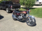
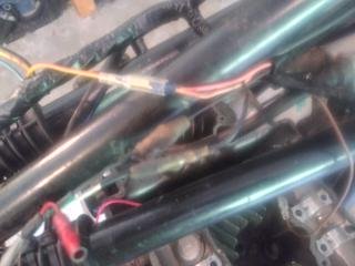
Slowly working my way through this. I've got most of the connections in the headlight bucket and the tail section. Called Z1 Parts and they're sending me out a pair of single wire turn signals. Been using my KZ900 a lot to get an idea for the harness routing. I apologize for the poor pics. The poor light must have slowed the shutter speed way down on my phone. In pic 1, Not sure of the brown and pinkish orange females coming from the new harness... has to be turn signal flasher. Then pic two... This is the PO's hookup of the regulator rectifier. The 3 yellows from the alternator are going to the 3 yellows from the regulator rectifier. Brown from the alternator is taped off. Red from the regulator rectifier is unattached ... which I'm thinking goes to the battery? What about the brown from the alternator that's taped off? Then there's the 3 wire right above and to the right of the 3 yellow connection from the RR, a black yellow, blue and brown that are coming off the new harness. Still trying to figure them out. Pic 3 shows the coil hookup. Have the yellow/red going to the colored on the coils.. they're pink now, assuming they used to be red? Then the green and black from the ignition module are going to the black on each coil. There's a red female coming off the ignition with the green and black that's got me guessing also. I'd appreciate any of your thoughts on what's been done and any of the mystery wires... and thanks for all your advice to date.


KZ900; Z1
Last edit: 14 Jun 2021 17:37 by Robb2018.
Please Log in or Create an account to join the conversation.
- 73z1
-
- Offline
- Sustaining Member
- Posts: 463
- Thanks: 115
Re: Z1 Color Wiring Diagram?
14 Jun 2021 17:53
The two wires with spade connectors are for the flasher relay which hangs on right side of tool tray.
Original alternator wires are yellow, pink, blue.
Original alternator wires are yellow, pink, blue.
The following user(s) said Thank You: Robb2018
Please Log in or Create an account to join the conversation.
- Robb2018
-
Topic Author
- Offline
- User
- 76 KZ900 73 Z1 A
- Posts: 274
- Thanks: 29
Re: Z1 Color Wiring Diagram?
14 Jun 2021 18:27 - 14 Jun 2021 19:00
There's 3 yellows coming off the alternator which he has connected to 3 yellows on the RR. What's confusing is there's a brown and purple in that bundle coming off the alt and they're taped off going no where. I guess I need to open up the alt again to see what's on that side.
KZ900; Z1
Last edit: 14 Jun 2021 19:00 by Robb2018.
Please Log in or Create an account to join the conversation.
- hardrockminer
-
- Offline
- Sustaining Member
- Posts: 3008
- Thanks: 1106
Re: Z1 Color Wiring Diagram?
14 Jun 2021 20:10 - 14 Jun 2021 20:11
One goes to your oil pressure bypass and the other goes to the neutral switch down by the front sprocket. I can't remember for sure which is which but I think the purple goes to the neutral switch.
I have several restored bikes along with a 2006 Goldwing with a sidecar. My wife has a 2019 Suzuki DR 650 for on and off road.
Last edit: 14 Jun 2021 20:11 by hardrockminer.
The following user(s) said Thank You: Robb2018
Please Log in or Create an account to join the conversation.
- slmjim+Z1BEBE
-

- Offline
- User
- Enjoy Life! IT HAS AN EXPIRATION DATE!
- Posts: 1274
- Thanks: 781
Re: Z1 Color Wiring Diagram?
15 Jun 2021 05:59
Brown is voltage sensing used on the old, separate regulator. Not needed on modern combined reg/rec units.
Oil pressure sw. is blue, transitioning to blue/red tracer on the other side of the 5 pin connector.
Hard to tell from the diagram color key, but the neutral sw. is probably red/blue tracer.
Not seeing purple anywhere on the wiring diagram. Is there a purple that is coming directly out of the alt. bundle, or in the main harness? Better pic?
Good Ridiun'
slmjim & Z1BEBE
A biker looks at your engine and chrome.
A Rider looks at your odometer and tags.
1973 ('72 builds) Z1 x2
1974 Z1-A x2
1975 Z1-B x2
1993 CB 750 Nighthawk x2
2009 ST1300A
www.kawasaki-z-classik.com
An enthusiast's forum focused exclusively
on all things Z1, Z2 and KZ900.
A Rider looks at your odometer and tags.
1973 ('72 builds) Z1 x2
1974 Z1-A x2
1975 Z1-B x2
1993 CB 750 Nighthawk x2
2009 ST1300A
www.kawasaki-z-classik.com
An enthusiast's forum focused exclusively
on all things Z1, Z2 and KZ900.
Please Log in or Create an account to join the conversation.
- Robb2018
-
Topic Author
- Offline
- User
- 76 KZ900 73 Z1 A
- Posts: 274
- Thanks: 29
Re: Z1 Color Wiring Diagram?
17 Jun 2021 17:30
The PO has the alternator wired directly to the RR instead of going through the panel with the blue and green connectors. Does anyone see any advantage or disadvantage to doing it this way?
KZ900; Z1
Please Log in or Create an account to join the conversation.
- 73z1
-
- Offline
- Sustaining Member
- Posts: 463
- Thanks: 115
Re: Z1 Color Wiring Diagram?
17 Jun 2021 18:08
White connector is rectifier, Green connector is voltage regulator.
My guess is your parts are not z1 and came from another bike so no connector.
My guess is your parts are not z1 and came from another bike so no connector.
Please Log in or Create an account to join the conversation.